A 1 MLD label gives you a daily flow reference, not a complete plant design. To specify equipment that survives production peaks and changing wastewater chemistry, you must convert operating data into hydraulic and pollutant loads, test each stream, select compatible treatment stages, and define measurable performance conditions.
Key takeaways
- Design for batch peaks, not only 1,000 m³/day average flow.
- Measure pollutant loads before sizing biological and sludge-handling systems.
- Segregate toxic, high-strength and stormwater streams before treatment.
- Specify outlet limits, sampling points and acceptance tests at the facility.
Turn the production schedule into a hydraulic design basis
A 1 MLD plant is justified only when the production schedule and water balance support about 1,000 m³/day, not because the nominal size sounds suitable. At average flow, that equals 41.7 m³/h; it does not cover instantaneous batch discharges, shift changes or washdowns.
Build the hydraulic design basis from these records:
- Measure water use and wastewater generation for each process, cleaning activity and utility, then separate sanitary sewage and uncontaminated stormwater.
- Record operating days per year or month, production shifts, shutdowns, seasonal changes and planned expansion.
- Calculate average daily flow from the total wastewater volume divided by operating days, and calculate peak hourly flow from an hourly profile.
- Record every batch discharge volume, release time and duration; a 300 m³ batch released in three hours creates a 100 m³/h hydraulic event.
- Size equalization from an hourly flow balance, including inflow, discharge to treatment and storage volume. Do not select its volume from a generic retention time.
Headworks, transfer pumps, clarifiers and tertiary equipment must pass the documented peak hourly flow or peak batch flow. Equalization moderates that peak but does not make an undersized inlet disappear. Keep stormwater outside the ETP unless the design specifically includes it.
Add capacity for identified cleaning water, abnormal batches, seasonal peaks and approved future expansion, then state that margin in cubic metres per day and cubic metres per hour. Finally, check pollutant loading: at 1 MLD, each 1 mg/L of a constituent equals 1 kg/day, so hydraulic capacity alone cannot confirm treatment capacity.
Measure pollutant loading instead of designing from flow alone
At 1 MLD, every 1 mg/L of an influent constituent equals 1 kg/day of load. A 1,000 m³/day stream with high COD, oil, metals, salinity or toxicity can therefore overwhelm a plant that looks adequate on hydraulic flow alone.
1. Measure total flow continuously and log it hourly, including batch discharges, shift changes, cleaning water and non-production periods. Record production campaign, operating hours and discharge point for every sample.
2. Collect flow-proportional composite samples across complete operating days and repeat them during different products, seasons and production campaigns. Include cleaning events; one normal-day composite can hide a short toxic slug.
3. Take same-time grab samples for rapidly changing or poorly preserved parameters: pH, temperature, dissolved oxygen, residual chlorine, sulfide and volatile compounds. Sample separate streams before combining them if segregation or pretreatment is under consideration.
4. Test COD, BOD, TSS, TDS and conductivity, plus oil and grease, ammonia, total nitrogen, phosphorus, sulfate, sulfide, chloride, colour, heavy metals, solvents and other site-specific chemicals. Add toxicity or inhibition testing where biological treatment could be affected.
5. Calculate hourly and daily mass loads, not concentrations alone, and document minimum, average and peak values. Ask the laboratory for preservation methods, holding times and detection limits.
Use those results to size equalization from an hourly flow-and-load mass balance rather than a generic retention time. Test settleability and sludge-volume index when solids separation is planned; a clarifier with enough volume can still lose solids during peak hydraulic or solids loading.
Separate incompatible streams and build the right treatment train
A solvent slug can disable an otherwise healthy biological process within one discharge cycle. Keep high-strength, toxic, hot, or extreme-pH batches in a segregated sump with a controlled transfer point; dilution is not a substitute for inhibitor removal.
| Stream | Pretreatment | Downstream route |
|---|---|---|
| General process wastewater with solids | Screening, grit removal, and an equalisation tank | Biological treatment, followed by clarification and polishing |
| Oily wash water | Screening, oil separation, and controlled equalisation | Biological treatment after free oil is removed; send recovered oil to approved disposal |
| Acidic or alkaline cleaning liquor | Separate collection and neutralization with automatic pH control | Equalised flow to biological treatment after pH stabilises |
| Metal-bearing wastewater | pH adjustment, coagulation-flocculation, and precipitation with sludge removal | Biological treatment only after dissolved-metal limits are met |
| Solvent, biocide, or toxic batch | Isolated storage, testing, and adsorption or oxidation where validated | Biological treatment only after inhibition testing confirms compatibility |
| High-TDS or saline wastewater | Segregated collection; screening and solids removal do not reduce dissolved salts | Membrane or evaporative treatment, with concentrate storage and disposal |
Route concentrated streams to their own treatment stage instead of sending them to a common sump. A shared equalisation tank needs level control, mixing, overflow protection, and a normally closed bypass; otherwise one wrong valve can contaminate every downstream process.
Specify standby pumps and blowers for critical equipment, but also define where an upset batch goes during power or instrument failure. N+1 equipment does not protect a plant if emergency storage or concentrate disposal is already full.
Choose biological treatment around chemistry, oxygen demand and sludge
A 1 MLD flow does not determine the biological process; biodegradable COD, toxicity, salinity, oxygen demand, nutrient limits and operating pattern do. Remove oil, metals, solvents, extreme pH and inhibitory chemicals before biology. Dilution is not a dependable cure for an inhibitor.
| Option | Best fit | Main design trade-off |
|---|---|---|
| MBBR | Variable industrial loading where robust attached growth is valuable and space is limited | Handles load swings well, but still needs downstream solids separation and media retention screens |
| Activated sludge | Biodegradable wastewater with reasonably stable flow and sufficient land for tanks and clarifiers | Flexible and familiar, but produces more waste activated sludge and suffers under toxic slugs |
| SBR | Intermittent or batch discharge where one tank can fill, react, settle and decant in cycles | Avoids a continuous clarifier, but needs equalization, automation and enough tanks for uninterrupted operation |
| MBR | Tight suspended-solids limits, water reuse or a small footprint after reliable pretreatment | Produces high-quality effluent, but membrane fouling, cleaning chemicals and energy raise operating demands |
| Anaerobic treatment | High-strength, readily biodegradable COD where biogas recovery is useful | Generates less biological sludge and little aeration demand, but requires post-treatment for residual COD, nutrients, sulfide and pathogens |
Size aeration from measured oxygen demand, not COD alone. Nitrification consumes 4.57 g oxygen and 7.14 g alkalinity as CaCO3 per gram of ammonium nitrogen oxidized; denitrification also needs usable carbon.
Include waste activated sludge and chemical sludge quantities, thickening or storage, dewatering, cake transport and disposal. Sludge containing metals, solvents or other hazardous constituents needs separate classification and disposal controls.
Write a specification that can be tested at the operating facility
Do not accept a 1 MLD ETP on equipment capacity alone. Require a site acceptance test that proves treated effluent meets every applicable parameter in the consent conditions and the governing CPCB and MoEFCC standards for your industry, discharge route and reuse purpose.
1. State the design envelope: inlet flow, peak hourly flow, pollutant concentration ranges, temperature, pH, operating hours, production campaigns, cleaning chemicals and sludge age. Include the hydraulic limit and loading limit separately.
2. Define each guaranteed outlet limit for pH, BOD, COD, TSS, oil and grease, ammonia, total nitrogen, phosphorus, colour, metals, salinity and any industry-specific contaminant. Add the sampling location, preservation method, laboratory method and reporting units.
3. Require flow-proportional sampling over an agreed test period that includes production peaks, cleaning events and normal shifts. Take separate grab samples for fast-changing parameters such as pH, temperature, dissolved oxygen, residual chlorine, sulphide and volatile compounds.
4. Specify the performance guarantee with permitted exclusions, test duration, influent conditions and failure remedy. A short test using synthetic or dilute wastewater proves little.
5. Test standby pumps, blowers, alarms, bypass prevention, emergency storage and restart after power loss. Record flow, energy, chemical dose, dissolved oxygen, sludge wasting and operator interventions.
NEEL GUARD AQUA SYSTEMS should provide these documents before commissioning: process calculations, mass balance, equipment datasheets, control logic, calibration certificates, operating procedures, maintenance schedules and as-built drawings. Without them, compliance cannot be independently verified.
Related product
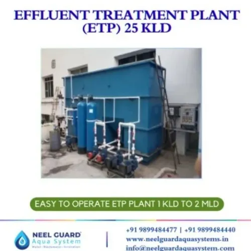
 | EFFLUENT TREATMENT PLANT (ETP) EFFLUENT TREATMENT PLANT 1 MLD ₹8500000 A 1 MLD (Million Liters per Day) Effluent Treatment Plant is a high-capacity wastewater treatment solution designed for industries to treat and... View product → |
Frequently asked questions
How should production schedules affect a 1 MLD ETP design?
Convert production volumes, operating shifts, washdowns and batch discharges into an hourly water balance. A 1 MLD average flow equals about 41.7 m³/h, but equalization capacity must address short-duration peaks.
Why is flow alone insufficient for sizing an effluent treatment plant?
Treatment equipment depends on pollutant loading as well as flow. Measure parameters such as COD, BOD, TSS, pH, oil and grease, nutrients, temperature and toxic compounds to calculate mass loads.
Which industrial wastewater streams should be separated?
Keep incompatible streams apart when they contain acids, alkalis, solvents, oils, toxic chemicals, high solids or unusually high organic strength. Separate clean stormwater from contaminated process effluent.
How do you choose biological treatment for an industrial ETP?
Match the biological process to biodegradability, oxygen demand, chemical inhibition, nutrient balance, temperature and sludge production. Confirm that pretreatment protects microorganisms from shock loads.
What should an ETP performance specification include?
State inlet design conditions, treated-water limits, flow and load ranges, sampling locations, test methods, operating conditions and acceptance tests performed at the operating facility.