A 25 KLD rating tells you the plant’s daily hydraulic capacity, not whether it can handle your pollutant load, batch discharges or reuse target. You will be able to verify the required capacity, define the treatment train, compare biological options and prepare a site-ready specification before requesting quotations.
Key takeaways
- Confirm hourly flow and peak discharge before selecting 25 KLD capacity.
- Test COD, BOD, TSS, pH, oil and sector-specific contaminants.
- Use equalisation and adequate storage to handle production peaks and shock loads.
- Choose discharge, reuse or recovery targets before finalising the treatment train.
Confirm that 25 KLD matches your real wastewater flow
A 25 KLD ETP capacity is designed for 25,000 litres per day, not a single 25,000-litre discharge. At a uniform 24-hour rate, that equals 1.04 m³/h; an eight-hour production shift averages 3.13 m³/h before peaks. Size from the site’s hourly pattern, or pumps and tanks may be undersized despite an acceptable daily total.
Establish the design flow with industrial wastewater flow measurement at each relevant drain or collection point, then reconcile readings with production records. Do not divide a monthly water bill by 30: freshwater can enter products, cooling systems, toilets or evaporation, while reuse and rainwater distort the result.
- Record weekday and weekend flows during production, start-up, shutdown and cleaning.
- Plot hourly volumes and identify the highest sustained rate and the largest short discharge; this is the peak discharge analysis.
- Repeat readings across production batches and seasonal conditions, then include confirmed future expansion.
- Check whether any drain bypasses the proposed collection tank or carries concentrated waste outside the common ETP.
Compare the measured daily volume with 25,000 litres and the peak hourly rate with inlet-pump and tank capacity. Batch releases, shift changes and chemical cleaning can create hydraulic or toxic shocks, so provide equalisation storage based on the hourly flow profile; 6–12 hours is a preliminary allowance, not a final sizing rule.
Measure pollutant loading before choosing the treatment process
A 25 KLD plant is adequate only when both hydraulic flow and pollutant mass loading fit its design. At 25 m³/day, wastewater containing 1,000 mg/L COD delivers 25 kg COD/day; at 100 mg/L, it delivers 2.5 kg/day. That difference changes aeration, reactor volume and sludge production.
Obtain representative samples during normal production and peak discharge. Use a flow-proportional composite sample for COD, BOD and TSS, plus grab samples for pH, temperature, oil and grease, metals and toxic chemicals. Ask an accredited laboratory for analysis covering:
| Characteristic | Test | Why it affects selection |
|---|---|---|
| COD and BOD | Dichromate COD; five-day BOD | Sets biological and aeration loading |
| TSS and oil | Gravimetric TSS; oil-and-grease test | Determines screening, separation and clarification needs |
| pH and temperature | Calibrated pH testing and temperature measurement | Reveals conditions that inhibit biological treatment |
| Conductivity and TDS | Conductivity meter; TDS test | Identifies dissolved salts that biological treatment will not remove |
| Metals and toxicants | ICP or AAS metals testing; sector-specific toxicity tests | Signals precipitation, adsorption or segregation requirements |
Compare the laboratory analysis with the proposed reactor loading, not only the 25 KLD flow label. Check salinity, solvents, biocides and heavy metals before sending concentrated streams to biology; equalisation, neutralisation, recovery or separate disposal may be necessary. Repeat COD, BOD, TSS, pH and conductivity testing across production batches before finalising the process.
Build the treatment train around shock loads and sector-specific contaminants
A 25 KLD plant needs protection before biology. Use screening for rags and grit, oil separation for free oil, an equalisation tank for flow and pollutant buffering, and pH correction before chemical or biological treatment.
Send concentrated solvents, plating baths, high-salinity regenerant, CIP chemicals, and strong acid or alkali to separate recovery, neutralisation, precipitation, or disposal routes; dilution can poison the biomass rather than solve the problem.
Select the remaining stages from the contaminants you measured:
- Use coagulation-flocculation followed by primary clarification for colour, fine solids, metals, and colloidal material.
- Add dissolved-air flotation instead of relying only on settling when emulsified oil, fats, or very fine solids would cause foaming, poor settling, or membrane fouling.
- Use secondary clarification after biological treatment, then filtration and disinfection when the outlet requires low suspended solids or hygienic reuse.
- Choose an aerobic process that tolerates variable loading, and monitor pH, dissolved oxygen, conductivity, temperature, and key toxicants at the inlet.
| Process option | Strength | Use it when |
|---|---|---|
| MBBR | Attached biomass handles load swings with simpler continuous operation | Flow and organic load vary, but toxicity is controlled |
| SBR | Fill, react, settle, and decant in timed batches | Discharge arrives in batches and operating staff can manage cycles |
| MBR | Produces low-solids effluent in a compact footprint | Reuse needs membrane-quality water and pretreatment is reliable |
Biological treatment will not remove dissolved salts reliably. Add softening, filtration, reverse osmosis, or evaporation only after defining concentrate disposal; oversized blowers and poorly clarified effluent turn energy use and membrane fouling into avoidable costs.
Set the outlet target: discharge, reuse or higher-quality recovery
At 25 KLD, the outlet destination determines the final treatment stages, monitoring plan and waste-disposal burden. Quote the actual consent or reuse specification; industrial wastewater discharge limits differ for inland surface water, public sewer, land application and site-specific directions.
| Option | Treatment emphasis | Compliance consequence |
|---|---|---|
| Discharge | Clarification, polishing filtration and verified disinfection | Test the parameters named in the consent, including BOD, COD, TSS, pH, oil and grease, metals or colour |
| Cooling water reuse | Reliable TSS removal, filtration, disinfection and conductivity control | Check scaling, corrosion, biological growth and cycles of concentration before accepting the water |
| Higher-quality recovery | Ultrafiltration for fine solids and reverse osmosis for dissolved salts | Define RO reject, membrane-cleaning chemicals and concentrate disposal before approval |
A biological stage can reduce BOD without reducing TDS. If conductivity or hardness threatens cooling equipment, add softening, ultrafiltration or reverse osmosis based on the feed analysis rather than the 25 KLD label.
Specify disinfection by organism-reduction target, contact time and flow, not by nominal capacity alone. UV loses effectiveness when turbidity, colour or suspended solids remain high and leaves no residual in storage; chlorine provides residual protection but needs dose control and by-product monitoring.
Destination also changes sludge planning. Coagulation, precipitation and membrane pretreatment can increase sludge or concentrate volumes, so include thickening, dewatering, covered storage, spill control and an authorised disposal route. Segregate solvents, plating solutions, strong acids, alkalis and high-salinity regenerant before they reach the common ETP.
Specify the plant around the site, not only the process diagram
Compare supplier proposals against the site, not just the equipment list. Require drawings and guarantees showing where wastewater enters, how treated water leaves, and how operators isolate each stage without sending untreated flow to a drain.
| Proposal item | Ask supplier to show | Why it matters |
|---|---|---|
| Hydraulics | Invert levels, gravity or pumped transfer, equalisation volume, peak-flow pump capacity, flood level and stormwater exclusion | A 25 KLD average is 1.04 m³/h, but an eight-hour shift produces about 3.13 m³/h before peaks |
| Process choice | Design basis and operating cost for MBBR, SBR or MBR, including aeration power, cycle controls, membranes and spare parts | The lowest equipment price can create the highest electricity, operator and replacement burden |
| Site installation | Tank footprint, ventilation, electrical load, chemical unloading route, crane or access space, and sludge-removal access | An inaccessible blower, pump or sludge tank will remain broken |
| Compliance controls | Online pH, flow recording, sampling points, alarm logic, bypass prevention and outlet guarantees tied to your measured loads | A biological stage does not remove TDS; reuse may need filtration, RO or concentrate disposal |
Ask NEEL GUARD AQUA SYSTEMS to mark these interfaces on a site layout before fabrication, including cable routes and safe chemical storage.
Compare sludge thickening, dewatering, spill containment, temporary storage and authorised disposal documentation separately. Chemical precipitation can generate far more sludge than biological treatment, turning an apparently compliant liquid outlet into a site liability.
Related product
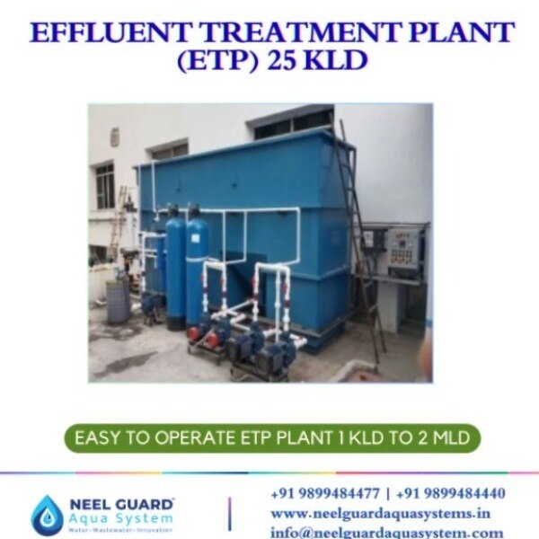
 | EFFLUENT TREATMENT PLANT (ETP) EFFLUENT TREATMENT PLANT 25 KLD ₹550000 The 25 KLD Effluent Treatment Plant (ETP) by Neel Guard Aqua Systems is a high-performance wastewater treatment solution designed to treat 25,000... View product → |
Frequently asked questions
How do you confirm that 25 KLD matches actual wastewater flow?
Measure daily volume, hourly production flow, shift timing and peak discharge. A 25 KLD plant handles 25,000 litres per day, but its tanks and pumps must also handle the hourly pattern.
Which wastewater tests are needed before selecting an ETP process?
Test pH, BOD, COD, TSS, oil and grease, and sector-specific contaminants. Use the results to calculate pollutant loading rather than selecting equipment from flow alone.
Why must an ETP account for shock loads?
Batch discharges, cleaning chemicals and production changes can sharply alter flow or pollutant concentration. Equalisation and suitable chemical, biological or physical treatment protect downstream units.
How does the intended outlet affect ETP design?
Discharge, internal reuse and higher-quality recovery require different treatment stages and outlet targets. Define the destination and required water quality before specifying the process train.