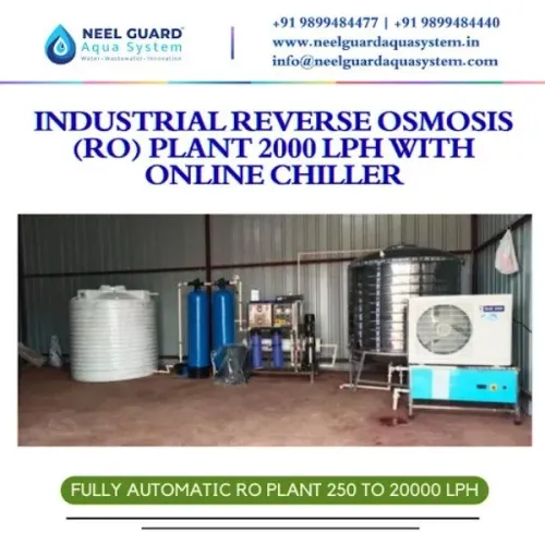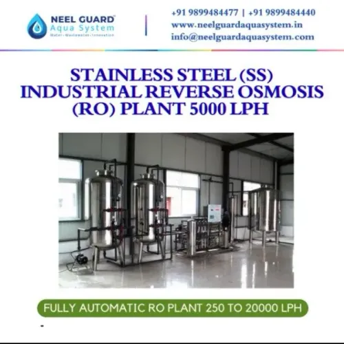
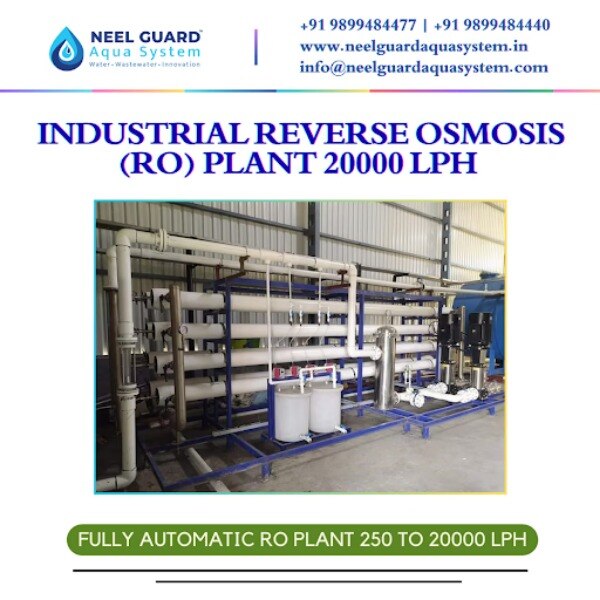
A 20,000 LPH label does not tell you how much treated water will reach production, how much feed water will become reject, or whether the plant fits your utility area. You will be able to size the system against demand, define the pretreatment and storage it needs, and compare supplier proposals using measurable acceptance criteria.
Key takeaways
- Size output against peak hourly demand, operating hours and storage capacity.
- Expect usable permeate below 20,000 litres per hour after recovery losses.
- Specify feed-water analysis, pretreatment, recovery, reject flow and utilities.
- Compare guaranteed water quality, testing methods, exclusions and commissioning records.
How do you determine whether 20,000 LPH matches your facility’s demand?
A 20,000 LPH RO plant matches your facility only when its usable output, operating schedule and storage arrangement cover demand under the worst planned condition. Base 20,000 LPH RO plant sizing on actual hourly water demand, not the nameplate figure.
Separate average demand from peak water consumption. Record operating hours and add water for:
- Cleaning and sanitization
- Laboratory use
- Utilities, including boilers and cooling
- Planned production growth
A plant producing 20 m³/h makes 160 m³ during an 8-hour shift and 480 m³ during 24-hour operation, before downtime.
| Operating schedule | RO output before downtime | Compare it with |
|---|---|---|
| 8 hours at 20 m³/h | 160 m³/day | Daily demand and largest simultaneous draw |
| 24 hours at 20 m³/h | 480 m³/day | Daily demand, peak demand and reserve |
If daily demand is 180 m³, an 8-hour schedule fails without storage; a 24-hour schedule provides more production time but not automatic reserve. Check whether the largest simultaneous draw exceeds 20 m³/h.
RO storage tank sizing must use peak demand, the RO operating schedule and required reserve, not an arbitrary number of production hours. Calculate reserve for the longest power interruption, membrane cleaning, pretreatment backwash and one unavailable train. For example, reserve volume equals demand during that event period plus planned cleaning and backwash volumes.
A tank absorbs short peaks and lets the RO run during lower-demand periods, but specify hygienic geometry, recirculation, level control and sanitization to prevent stagnant water.
How much usable water does a 20,000 LPH RO plant actually deliver?
A 20,000 LPH rating normally means 20 m³/h of permeate, not feed-water flow. At 75% RO recovery percentage, the RO reject water calculation is 20 ÷ 0.75 = 26.7 m³/h feed and 6.7 m³/h concentrate. At 60% recovery, it requires 33.3 m³/h feed and produces 13.3 m³/h concentrate.
That is rated output under stated temperature, pressure and salinity conditions, not guaranteed delivered production. Subtract startup, pretreatment backwash, membrane cleaning and other downtime when calculating usable water.
Use permeate flow temperature correction: a 25°C design can lose roughly 2–3% output for each 1°C drop, while higher salinity, lower pressure and membrane ageing also reduce flow.
Recovery cannot be selected from output alone. Calcium carbonate, calcium sulfate, silica, barium sulfate, strontium sulfate, iron and aluminium can limit the target through scaling or fouling. Raising recovery reduces concentrate volume but increases concentration-side risk.
| Train arrangement | Output when one train is unavailable | Practical meaning |
|---|---|---|
| One 20 m³/h train | 0 m³/h | Full shutdown during cleaning or maintenance |
| Two 10 m³/h RO duty and standby trains | 10 m³/h | Partial supply; storage must cover the shortfall |
| Two 20 m³/h trains | 20 m³/h | Full-capacity redundancy, if utilities and pretreatment support both |
Two smaller trains do not automatically provide full redundancy. Specify the required output with one train unavailable, then size RO duty and standby trains, storage and feed capacity to that condition. A two-stage array can control tail-element loading, but its design must follow feed analysis and end-of-life output.
What feed-water analysis and pretreatment must be specified before ordering?
1. Give the supplier a laboratory RO feed-water analysis and an operating range covering seasonal minimum and maximum values, not conductivity alone. Include TDS or conductivity, hardness, alkalinity, sulfate, silica, iron, manganese, turbidity, SDI, pH, temperature, free chlorine, chloramine and microbiological condition.
A single sample can hide winter temperature changes, intermittent oxidant dosing or a high-silica well-water event.
2. Use those results to set membrane selection, design flux, operating pressure and recovery. Hardness, alkalinity and sulfate determine carbonate or sulfate scaling risk; silica can limit recovery; iron and manganese can foul membranes. The analysis also determines antiscalant dosing, pH adjustment and whether softening is needed. Turbidity and SDI identify particulate-fouling risk.
3. Specify the RO pretreatment system as a complete sequence:
- Raw-water storage, sized with mixing, level control and drain access.
- Multimedia filter for suspended solids, turbidity and SDI reduction.
- Iron or manganese removal when analysis shows those contaminants.
- Activated carbon filter for chlorine and organic matter.
- Softener or antiscalant dosing for hardness control.
- Cartridge filtration before high-pressure pumping.
- RO dechlorination before polyamide membranes.
Free chlorine and other oxidants damage polyamide membranes. Chloramine removal may require greater carbon capacity or a dedicated dechloramination step than chlorine removal. Install oxidant monitoring after dechlorination, and define backwash, regeneration, chemical-dosing and drain requirements before ordering. These provisions prevent unplanned downtime and protect the membrane from oxidation and fouling.
What site, utility and concentrate details must the plant design include?
A 20,000 LPH label becomes a buildable design only when it includes the site layout, utilities and waste-water route. Request the RO plant electrical load and energy consumption at the stated feed-water temperature, salinity, pressure and recovery.
For brackish water, 0.5–1.5 kWh/m³ implies roughly 10–30 kW for the RO process at 20 m³/h, excluding pretreatment, controls and standby equipment.
1. Specify the high-pressure pump duty, operating pressure, design flux, specific energy consumption and RO membrane configuration. Show the number of stages, pressure vessels and elements, plus permeate, feed and concentrate flows at start-of-life and end-of-life.
The industrial RO plant footprint must include the skid, cartridge filters, electrical panel, chemical systems, service clearances, lifting access and membrane-removal space.
2. Put inlet, permeate and concentrate pipe sizes on the drawing. Show drain routing, air gaps, floor drainage and access for pumps, vessels and cleaning equipment; an undersized drain can flood the skid during backwash or cleaning.
3. Require a concentrate balance and documented RO concentrate disposal route. At 75% recovery and 24-hour operation, approximately 6.7 m³/h of reject equals 160 m³/day. Check sewer limits, chemical residuals, temperature, reuse options, evaporation capacity and permits before fixing recovery.
4. If permeate is stored, specify hygienic tank geometry, protected vent filtration where appropriate, level controls, continuous recirculation, cleanability and sanitization. Install flow, pressure, temperature, conductivity, pH and tank-level instruments so pretreatment failure and membrane fouling appear before output collapses.
How should you compare proposals and verify performance after installation?
Every proposal should use the same feed-water basis; otherwise a 20,000 LPH claim cannot support an RO plant performance guarantee. Require feed temperature, pressure, salinity, recovery, membrane model, end-of-life output and guaranteed permeate quality.
| Measure | Require in proposal and commissioning record | Acceptance check |
|---|---|---|
| Feed and permeate | Flow, recovery, pressure by stage and temperature | Matches the stated design |
| Water quality | Conductivity or TDS and pH | Meets guaranteed limits |
| Membrane health | Normalized permeate flow and salt passage | Remains within agreed limits |
This record distinguishes temperature and pressure effects from fouling, which an instantaneous flow figure hides. Define commissioning records and acceptance limits before purchase, including the membrane array, reject route, utility loads, storage controls and one-train-out performance. Give the same data pack to NEEL GUARD AQUA SYSTEMS when requesting its design.
Set an RO CIP trigger at a 10% loss of normalized permeate flow, a 5–10% increase in normalized salt passage or abnormal differential pressure. Identify the foulant first, then match cleaning chemistry to it and the membrane manufacturer’s pH and temperature limits; the wrong chemical can damage the membrane.
Permeate conductivity alone does not establish pharmaceutical Purified Water. Carbon dioxide, boron, silica, microorganisms and endotoxin require separate evaluation, and Purified Water RO validation must cover the complete treatment train.
Related product
 | REVERSE OSMOSIS (RO) PLANTS ₹2150000 Neel Guard Aqua Systems offers a high-capacity 20,000 LPH Industrial Reverse Osmosis (RO) Plant, purpose-built for large-scale industrial and... View product → |
Frequently asked questions
How do you determine whether 20,000 LPH matches your facility’s demand?
Compare peak hourly purified-water demand with the plant’s actual permeate output, operating schedule and available treated-water storage. Include production peaks, cleaning cycles, downtime and the worst planned operating condition.
How much usable water does a 20,000 LPH RO plant actually deliver?
The 20,000 LPH figure is the rated permeate flow under defined feed-water and operating conditions. Usable daily volume depends on runtime, recovery, feed interruptions, cleaning, reject handling and storage capacity, so request guaranteed permeate flow at your specified conditions.
What feed-water analysis and pretreatment must be specified before ordering?
Provide a recent laboratory analysis covering TDS, hardness, alkalinity, pH, turbidity, SDI, iron, manganese, silica, chloride, sulphate, oil and microbiology. Specify filtration, antiscalant or softening, activated carbon, cartridge filtration, dosing and disinfection requirements from those results.
What site, utility and concentrate details must the plant design include?
Document feed pressure and temperature, electrical supply, installation footprint, drainage, chemical storage, access, ventilation, treated-water storage, reject flow, noise limits and cleaning provisions. Confirm where concentrate and cleaning waste will be discharged.
How should you compare proposals and verify performance after installation?
Compare membrane model, recovery, guaranteed permeate flow, conductivity, pretreatment equipment, energy use, instrumentation, exclusions and service scope. During commissioning, record feed conditions, permeate flow, recovery, pressure, conductivity and laboratory results against the agreed guarantee.