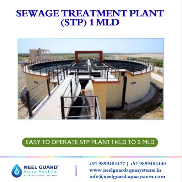
A 1 MLD sewage treatment plant may occupy only 500–1,000 m² in process equipment, yet the complete developed site can require about 2,000–5,000 m² once roads, sludge handling, utilities, clearances and expansion space are included. By the end, you will be able to test a plot, compare layout configurations and identify the civil, hydraulic, electrical and access provisions that must appear in a preliminary site plan.
Key takeaways
- Reserve 2,000–5,000 m² for a 1 MLD sewage treatment plant.
- Use compact layouts when land is limited and mechanical sludge dewatering is available.
- Include space for tank access, sludge movement, electrical equipment, and maintenance vehicles.
- Check hydraulic levels, soil conditions, flood risk, and expansion space before fixing the layout.
How Much Land Does a 1 MLD STP Actually Need?
Reserve roughly 2,000–5,000 m² of plot for a 1 MLD STP. Use the lower end for a compact, above-ground plant with mechanical sludge dewatering; move toward the upper end when drying beds, wide vehicle access, odor buffers or expansion are required.
The advertised 500–1,000 m² equipment footprint is only the process footprint versus plot area. The 1 MLD sewage treatment plant space requirement also includes inlet screening, sampling points, operator access, transformer and generator zones, chemical storage, internal roads, stormwater drainage, lifting clearances and setbacks. Those items determine the developed site area.
A practical preliminary allocation might use 800 m² for tanks and process equipment, 700 m² for roads, access and services, 500 m² for sludge handling and covered cake storage, and 500 m² for future treatment capacity. Confirm these allowances against the selected process and local setbacks before purchasing land.
- Reserve a dedicated sludge zone for polymer preparation, dewatering equipment, filtrate return, wash-water drainage, covered cake storage and truck loading. Drying beds require substantially more land and need removal access.
- Keep space around screens, blowers, pumps and disinfection equipment for isolation, lifting and duty/standby equipment; a tight layout turns routine maintenance into plant shutdowns.
- Provide a separate expansion area beside hydraulic and electrical services, not an isolated leftover corner.
- Keep clean roof and yard runoff out of the sewage system, and allow drainage, flood protection and finished-floor elevation work within the plot boundary.
How Should the Treatment Process and Civil Structures Fit on the Site?
The process should follow the hydraulic grade line, not the plot boundary. Set inlet and outlet levels after allowing for screen and grit-channel losses, biological-tank levels, clarifier or membrane losses, tertiary filtration, disinfection and treated-water storage; a higher receiving point then identifies the need for a final pumping station.
1. Place coarse screening, fine screening where required, grit removal and bypass isolation at the inlet. Show channel widths, operating water levels, screen-removal space, wash-water points, screenings storage and a route for lifting equipment. Provide isolation so one channel can be emptied without passing unscreened sewage forward.
2. Size the equalization tank for the selected balancing period and show its equalization tank dimensions, working volume, freeboard, mixer or aeration location, drain-down point and access opening. Keep roof or yard runoff out of this tank and the sewage inlet.
3. Position the biological treatment tank after equalization, with its operating level, freeboard, inlet and outlet structures, air-header routes and partition walls marked. Reserve a nearby blower room for duty/standby units, ventilation, acoustic control, isolation valves and removal of the largest blower.
4. Show the secondary clarifier dimensions, sludge-hopper levels, scraper or bridge envelope, scum-removal route and access for inspection and lifting. Keep return-sludge and waste-sludge pumps reachable without entering the tank area.
5. Follow clarification with tertiary treatment and disinfection, marking filter or membrane clearance, chemical-dosing access, contact volume, sampling points and treated-water storage. Draw a continuous maintenance route around every unit, including space to remove pumps, valves and covers.
Which Layout Configuration Changes the Space Requirement?
For a 1 MLD plant, a compact treatment package does not automatically mean a smaller plot: the layout shifts land from tanks to access, sludge handling, lifting zones and odor control.
| Configuration | Land use | Construction access | Sludge and odor implications | Future maintenance |
|---|---|---|---|---|
| Above-ground STP | Larger visible footprint; simple expansion | Easy excavation, delivery and crane access | Open sources need careful siting; drying beds consume substantial land | Best access to pumps, blowers, valves and tanks |
| Underground sewage treatment plant | Preserves surface space but needs excavation, shoring and structural cover | Difficult construction, dewatering and equipment replacement | Enclosure helps contain odors; sludge removal and ventilation need dedicated routes | Confined access increases lifting, inspection and repair time |
| Containerized STP | Small initial footprint with limited civil work | Fast placement, but trucks and cranes need clear approach | Sludge storage, dewatering and odor treatment remain external requirements | Replacement is straightforward only if removal paths remain clear |
| Hybrid STP layout | Places tanks below grade and equipment above ground | Balances excavation with accessible installation zones | Enclose headworks and sludge areas; keep cake loading outside buried structures | Provides practical access for blowers, controls and expansion |
Sludge handling often determines the final area. Mechanical dewatering needs polymer preparation, feed pumps, filtrate return, covered cake storage, wash-water drainage and truck loading; drying beds need more land and can create odor, vectors and weather delays.
Keep inlet works and sludge operations away from sensitive receptors, with extraction and scrubbing where enclosure is required. Reserve duty/standby equipment, isolation valves and lifting access, or a failed pump or blower can turn a compact layout into an unusable one.
What Access, Sludge and Electrical Infrastructure Must the Plot Include?
Set the STP internal road width at 3.5–4 m for one-way service traffic and about 6 m for two-way sludge-truck movement. Check turning radii against the actual truck, not a car, and keep a clear lifting zone beside screens, pumps, mixers and blowers.
Provide removable covers, a monorail or crane where a portable lifting vehicle cannot reach equipment.
| Infrastructure | Minimum planning provision | Why it matters |
|---|---|---|
| Access | Hardstand, turning area and vehicle clearance at inlet and sludge bays | Prevents blocked maintenance and loading operations |
| Sludge dewatering area | Dewatering machine, polymer system, feed pumps, filtrate return, wash-water drain, covered cake storage and truck loading | Keeps wet sludge, odour and runoff under control |
| Blower room | Duty/standby blowers, ventilation, acoustic treatment and blower room clearance around each unit | Allows removal, cooling and safe maintenance |
| Power | Transformer and DG space for STP, fuel access and fire separation | Supports process continuity during grid failure |
Size the generator for the essential load schedule, not only lights and controls. Include inlet pumping where used, aeration, return-sludge pumping, disinfection, instrumentation, communications and anti-discharge protection. A single critical pump or blower leaves the plant exposed; provide duty/standby units with isolation valves.
Route power and control cables in accessible, labelled trenches or trays, separated from wet wells and chemical lines. Crossings need sealed sleeves and drainage. Keep the sludge dewatering area under cover, with a wash-down drain and no path for filtrate to reach stormwater. Reserve space for future dewatering capacity and safe operator access.
How Do Hydraulic Levels, Ground Conditions and Expansion Affect the Final Plan?
Set the hydraulic grade line for STP before fixing any tank floor or platform. The STP inlet and outlet levels must accommodate losses through screening, grit removal, biological treatment, clarification or membranes, tertiary filtration and disinfection, then still reach the treated-water storage or receiving point.
If that point is higher than the outlet, include a final pumping station rather than discovering the problem after civil work.
1. Confirm the incoming sewer invert, actual peak hourly flow and discharge level. For a 1 MLD plant, the average is 11.6 L/s, but inlet works and pumps may need capacity around 2.5 to 3 times that flow when infiltration, inflow and daily variation justify it.
2. Survey the site before excavation. Record the flood level, finished-floor elevation, groundwater and waterproofing requirements, soil bearing capacity, seismic design conditions and stormwater drainage route. Confirm the flood level before STP construction; keep clean roof and yard runoff out of the sewage inlet.
3. Place critical equipment at maintainable elevations, with duty/standby pumps, blowers and lifting access. NEEL GUARD AQUA SYSTEMS should be asked to provide a level-and-head schedule showing every loss, operating water level, pump duty point and overflow route.
4. Draw the expansion zone before approving the layout. Keep a dimensioned, vehicle-accessible area for additional biological volume, tertiary treatment, sludge equipment, electrical capacity and pipe connections; do not consume it with parking or temporary storage.
A layout that passes average-flow calculations but ignores peak flow, flood protection or future pipe routes can become pump-dependent and expensive to rebuild.
Related product
 | SEWAGE TREATMENT PLANT (STP) ₹9500000 A 1 MLD (Million Liters per Day) Sewage Treatment Plant is a large-capacity, industrial-grade system designed to treat huge volumes of sewage water... View product → |
Frequently asked questions
How much land does a 1 MLD sewage treatment plant need?
Reserve roughly 2,000–5,000 m². Use less for a compact above-ground plant with mechanical sludge dewatering; allow more for drying beds, vehicle access, odor buffers, or expansion.
How should treatment units and civil structures fit on a 1 MLD STP site?
Arrange screening, grit removal, biological treatment, clarification, tertiary treatment, disinfection, and sludge handling in a sequence that supports gravity flow, safe access, and straightforward maintenance.
Which STP layout configuration uses the least space?
A compact above-ground arrangement with integrated or closely grouped treatment units uses less land than layouts with separate tanks, drying beds, long pipe runs, or large landscaped buffers.
What infrastructure must a 1 MLD STP plot include?
Provide an all-weather access road, turning space, screened inlet access, sludge-handling and dewatering areas, electrical and control rooms, chemical storage where required, drainage, and maintenance clearances.
How do hydraulic levels, ground conditions, and expansion affect the final STP plan?
Set tank levels to reduce pumping, confirm bearing capacity and groundwater conditions through a site investigation, check flood levels, and reserve an expansion zone before finalising the civil layout.