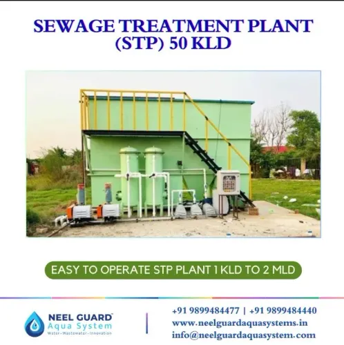
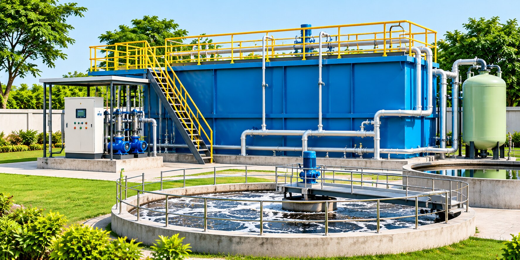
Sewage does not become reusable water in one tank: each stage removes a different contaminant and protects the equipment that follows it. By tracing the flow from collection through screening, biological treatment, clarification, filtration and disinfection, you can identify what each unit does, how the main plant configurations differ and whether a proposed capacity matches the actual wastewater load.
Key takeaways
- Screening and grit removal protect pumps and downstream treatment equipment.
- Aeration supplies oxygen for organic-matter removal and ammonia conversion.
- Size an STP using KLD, peak flow and wastewater load together.
- Check sludge handling, alarms, sampling points and design documents before approval.
From Collection to Equalization: Removing Debris, Grit and Flow Surges
Sewage collection carries wastewater through gravity sewers to an inlet chamber, where the incoming flow is measured and directed into preliminary treatment.
The screen chamber appearance and purpose are easy to recognise: it is a concrete channel or enclosed box containing a bar screen that intercepts rags, plastics, wipes and other debris before they blind pumps or foul downstream equipment.
- A bar screen removes large solids. Operators rake or mechanically lift the captured material for disposal; the screenings are not treatment credit.
- A grit chamber slows the flow without stopping it, allowing dense inorganic particles such as sand, gravel and eggshells to settle. Removing grit prevents abrasion and accumulation in pumps, aeration tanks and sludge equipment.
- Pumps raise sewage when site levels prevent gravity flow and regulate its transfer between units. Poorly protected pumps clog quickly.
- An equalization tank stores incoming wastewater and releases it at a controlled rate. Mixing prevents a morning surge, storm inflow or industrial batch from overwhelming clarifiers, filters or disinfection.
Equalization also smooths pH, temperature, salinity and pollutant concentration, but it cannot make a toxic solvent or metal safe by itself. Industrial sites need source control or pretreatment when those loads inhibit biological treatment.
Where used, primary settling then removes settleable solids and part of the suspended organic load; it does not remove dissolved BOD or ammonia, which require the biological stage.
The Biological Stage: How Aeration Tanks Remove Organic Matter and Ammonia
Microorganisms remove dissolved organic matter by using it as food: heterotrophs convert soluble carbon into carbon dioxide, water and new biomass. In an aeration tank, oxygen supports nitrifying bacteria that oxidize ammonia first to nitrite and then to nitrate.
An anoxic zone can then let denitrifiers convert nitrate to nitrogen gas; aeration alone does not remove nitrogen.
Primary settling removes settleable solids and some organic load, but soluble BOD and ammonia remain. The biological sequence is:
- Supply oxygen and mixing so organisms contact wastewater and maintain the required dissolved-oxygen conditions.
- Keep enough biomass in the system. Return activated sludge (RAS) preserves the solids inventory, while waste activated sludge (WAS) controls solids retention time and nitrification capability.
- Separate treated water from biomass after biological conversion. Excess sludge then requires thickening, stabilization and approved handling.
| Option | How the process changes | Main trade-off |
|---|---|---|
| Activated sludge process | Suspended flocs grow in the aeration tank; RAS returns settled biomass from a clarifier. | Flexible, but settling performance controls solids capture. |
| MBBR | Attached organisms grow on submerged MBBR media, so less biomass depends on recycling. | Compact and shock-tolerant, but media retention screens need maintenance. |
| SBR | Fill, react, settle and decant occur in one basin on a timed cycle. | Avoids a continuous-flow clarifier, but needs reliable level and cycle controls. |
| MBBR-SBR | Biofilm media and suspended sludge operate within batch cycles. | Adds biological resilience, with more complex controls. |
| MBR | Membranes replace final clarification and retain high biomass concentrations. | Produces low-solids effluent, but fouling demands cleaning and energy. |
Clarification, Filtration and Disinfection: Turning Mixed Liquor into Treated Water
The secondary clarifier separates biological solids from the mixed liquor by gravity. Settled biomass leaves through the sludge hopper as return activated sludge (RAS), which maintains solids in the aeration system; waste activated sludge (WAS) removes excess biomass and controls solids retention time.
The clear upper layer overflows, while poor settling, rising sludge or excessive peak flow can carry solids into the outlet.
A tertiary filter vessel removes fine suspended solids that escape clarification. Use it when the discharge permit requires lower TSS, phosphorus or pathogen-associated limits, or when reuse needs cleaner water. Chemical phosphorus precipitation can create particles for filtration, while denitrification requires a separate anoxic process; a filter alone does not remove dissolved nitrogen.
Filter loading depends on clarification quality. Solids carryover quickly increases headloss and backwash frequency, so inspect clarifier blanket depth, sludge volume index, mixed-liquor concentration and RAS rate before blaming the filter.
Disinfection inactivates remaining pathogens rather than removing solids. Chlorination uses a measured chlorine dose and contact time, with dechlorination before sensitive receiving waters or reuse; UV disinfection uses ultraviolet energy and needs low turbidity for effective exposure.
Store the disinfected effluent in a treated-water tank, then pump it to toilets, cooling, irrigation or another approved reuse point, or discharge it under the permit.
Sizing the Plant: Why KLD, Peak Flow and Wastewater Load Must Be Read Together
A 500 KLD package is not automatically suitable because KLD means kilolitres per day, an average-volume rating. Calculate domestic sewage from population × occupancy × per-person water use × the sewage-return fraction, then add commercial kitchens, toilets, laundries and other connected users.
| Design input | Calculation or check | Design consequence |
|---|---|---|
| Average flow | Daily sewage volume ÷ 24 = hourly flow | Sets biological and storage demand |
| Peak flow | Apply hourly and daily peaking factors to occupied-flow data | Sizes pumps, screens, clarifiers and filters |
| Infiltration and inflow | Add groundwater leakage and stormwater entering sewers | Prevents wet-weather overload |
| Wastewater load | Flow × BOD, TSS, ammonia and other concentrations | Sizes aeration and sludge systems |
| Industrial discharge | Map pH, temperature, salinity, solvents, metals and batch volumes | Requires segregation, pretreatment or equalization |
| Future expansion | Add approved occupancy, floor area or production growth | Reserves hydraulic and process capacity |
Peak-flow management is a treatment issue, not only a pipe issue. Storm inflow or an industrial batch can wash solids from a clarifier, overload filtration and shorten disinfection contact time while average KLD still looks acceptable.
Size the equalization tank from the volume arriving above the controlled treatment rate during the peak period, with allowance for mixing and usable freeboard. Do not use equalization to hide toxic shocks: source control and pretreatment must moderate inhibitory wastewater before biology.
Check the design against the permit’s flow, BOD5, TSS, nutrient, toxicity and pH limits. A plant with adequate aeration can still fail if peak hydraulic or solids loading causes final-settled sludge to escape.
Sludge, Controls and Design Checks Before You Approve an STP
Approve an STP only after its sludge mass balance shows where every kilogram goes. Primary sludge from a clarifier and waste activated sludge enter a sludge tank for thickening, stabilization, dewatering and approved disposal or reuse. Return activated sludge maintains solids in the aeration system; sludge wasting controls SRT and nitrification.
Anaerobic digestion can reduce volatile solids and produce biogas, while polymer conditioning and dewatering equipment determine the cake volume.
Use dissolved oxygen and ammonia monitoring to find failure before an effluent result exposes it. Check online nitrate, pH, temperature, oxidation-reduction potential, flow and turbidity readings, then reconcile them with calibrated instruments and laboratory results.
Low temperature, inadequate SRT, low oxygen, toxic influent or insufficient alkalinity can cause ammonia breakthrough while BOD and TSS still pass.
Ask NEEL GUARD AQUA SYSTEMS to show these items before you approve a customized design:
- Design basis: average and peak flow, BOD, TSS, ammonia, alkalinity, temperature and discharge limits.
- Process flow diagram, hydraulic profile, mass balance and piping-and-instrumentation diagram.
- Aeration calculations showing oxygen demand, blower turndown, anoxic volume, internal nitrate recycle and alkalinity demand.
- Clarifier solids loading, RAS and WAS ranges, sludge-tank volume, polymer trials and dewatering test results.
| Item | Compare | What failure it exposes |
|---|---|---|
| Blowers and diffusers | Installed oxygen capacity versus peak demand | Low DO and ammonia breakthrough |
| Sensors and controls | Sensor locations, calibration plan and manual backup | False stable readings |
| Pumps and standby units | Duty, standby, head and bypass arrangements | Sludge accumulation during outages |
Frequently asked questions
What happens to sewage before biological treatment?
The inlet stage measures incoming flow, removes large debris through screening, separates grit and manages flow surges through equalization.
How do aeration tanks remove organic matter and ammonia?
Aeration supplies oxygen to microorganisms that consume biodegradable organic matter; nitrifying bacteria convert ammonia during controlled biological treatment.
How does mixed liquor become treated water?
A clarifier separates biological solids from liquid, followed by filtration when required and disinfection before discharge or reuse.
Why must KLD, peak flow and wastewater load be considered together?
KLD describes average daily capacity, peak flow determines hydraulic loading, and wastewater load determines the biological treatment capacity required.
What should you check before approving a sewage treatment plant?
Review sludge handling, control-panel functions, alarms, sampling points, design calculations, equipment specifications and expected treated-water quality.